In today’s fast-paced, technology-driven world, Printed Circuit Boards (PCBs) and Printed Circuit Board Assemblies (PCBAs) are fundamental components in virtually every electronic device, from smartphones to industrial machinery. While often used interchangeably, PCBs and PCBAs serve distinct roles in electronics manufacturing and functionality.
This comprehensive guide explores the key differences, processes, and applications of PCB vs PCBA, helping you understand their unique contributions to modern electronics. Whether you’re a tech enthusiast, manufacturer, or someone curious about the inner workings of devices, this article will shed light on why both PCBs and PCBAs are essential in creating efficient and reliable electronic products.
What is a PCB?
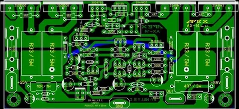
A Printed Circuit Board (PCB) is the backbone of almost every electronic device you use. It’s a flat board that connects all the components of a device, like resistors, capacitors, and microchips, so they can work together. Think of it as the wiring map that makes electronics function. Without PCBs, the gadgets we rely on every day—like phones, computers, and even cars—wouldn’t exist in their current compact and efficient form.
What is a PCB Made Of?
A PCB is made up of several layers, each with its own job to do. Here’s a breakdown of its main components:
- Substrate (Base Material)
This is the base of the PCB and gives it its strength and rigidity. The most common material used is FR4, a fiberglass-reinforced epoxy, because it’s durable, affordable, and great at insulating the board’s electrical components. Other materials like Teflon or metal may be used for specialized purposes. - Copper Layer
On top of the base is a thin layer of copper, which forms the actual circuits and pathways that allow electricity to flow. If the board is simple, it’ll have just one layer of copper. More complex designs might have multiple layers to handle intricate connections. - Solder Mask
On most PCBs, one finds the nearly usually green tinted coating discussed above. It shields these from moisture, dust, and also from inadvertent short circuits by covering the copper traces. It also directs solder movement during assembly to guarantee exact and clean connections. - Silkscreen
Topmost layer holding the text, symbols, and labels printed on it is the silkscreen. During assembly and repair, these labels enable technicians and manufacturers to locate and mark the components.
Types of PCBs
Available in several forms, Printed Circuit Boards, or PCBs, are intended to meet particular needs depending on complexity, adaptability, and utility, The most often occurring forms of PCBs are seen here:
1. Single-Layer PCB
- A single-layer PCB has one layer of conductive material (usually copper) on one side of the board.
- Features:
- Simple design and easy to manufacture.
- Ideal for low-cost and straightforward electronic devices.
- Applications:
Used in calculators, LED lighting, and home appliances.
2. Multi-Layer PCB
- Multi-layer PCBs consist of multiple layers of conductive material stacked together with insulating layers in between.
- Features:
- Supports complex circuits in compact designs.
- Offers higher connectivity and functionality.
- Requires advanced manufacturing techniques.
- Applications:
Found in smartphones, computers, medical equipment, and aerospace systems.
3. Flexible PCB
- Flexible PCBs are made of flexible materials like polyimide, allowing the board to bend or fold without breaking.
- Features:
- Lightweight and adaptable to irregular shapes.
- Durable under stress and vibration.
- Can reduce assembly complexity.
- Applications:
Common in wearable devices, cameras, and automotive electronics.
4. Rigid PCB
- Rigid PCBs are made of solid substrate materials that prevent them from bending or twisting.
- Features:
- Strong and durable.
- Provides a stable base for mounting components.
- Cannot be reshaped or bent.
- Applications:
Used in TVs, desktop computers, and industrial machines.
5. Rigid-Flex PCB
- A combination of rigid and flexible PCBs, rigid-flex boards have sections that are rigid and others that are flexible.
- Features:
- Combines the strengths of both rigid and flexible PCBs.
- Reduces the number of connectors needed.
- Simplifies complex designs.
- Applications:
Used in medical devices, military systems, and consumer electronics like smartphones and laptops.
6. High-Frequency PCB
- These PCBs are designed to transmit signals at high frequencies (usually above 1 GHz) with minimal signal loss.
- Features:
- Made with special materials like Teflon to ensure signal integrity.
- Requires precise design and manufacturing.
- Supports fast signal processing.
- Applications:
Common in radar systems, communication equipment, and satellite technology.
These several kinds of PCBs have diverse purposes that guarantee the devices operate as expected and in a broad field of applications. Selection thus depends on project needs concerning complexity, durability, and operating environment.
What is a PCBA?
Definition of Printed Circuit Board Assembly (PCBA)

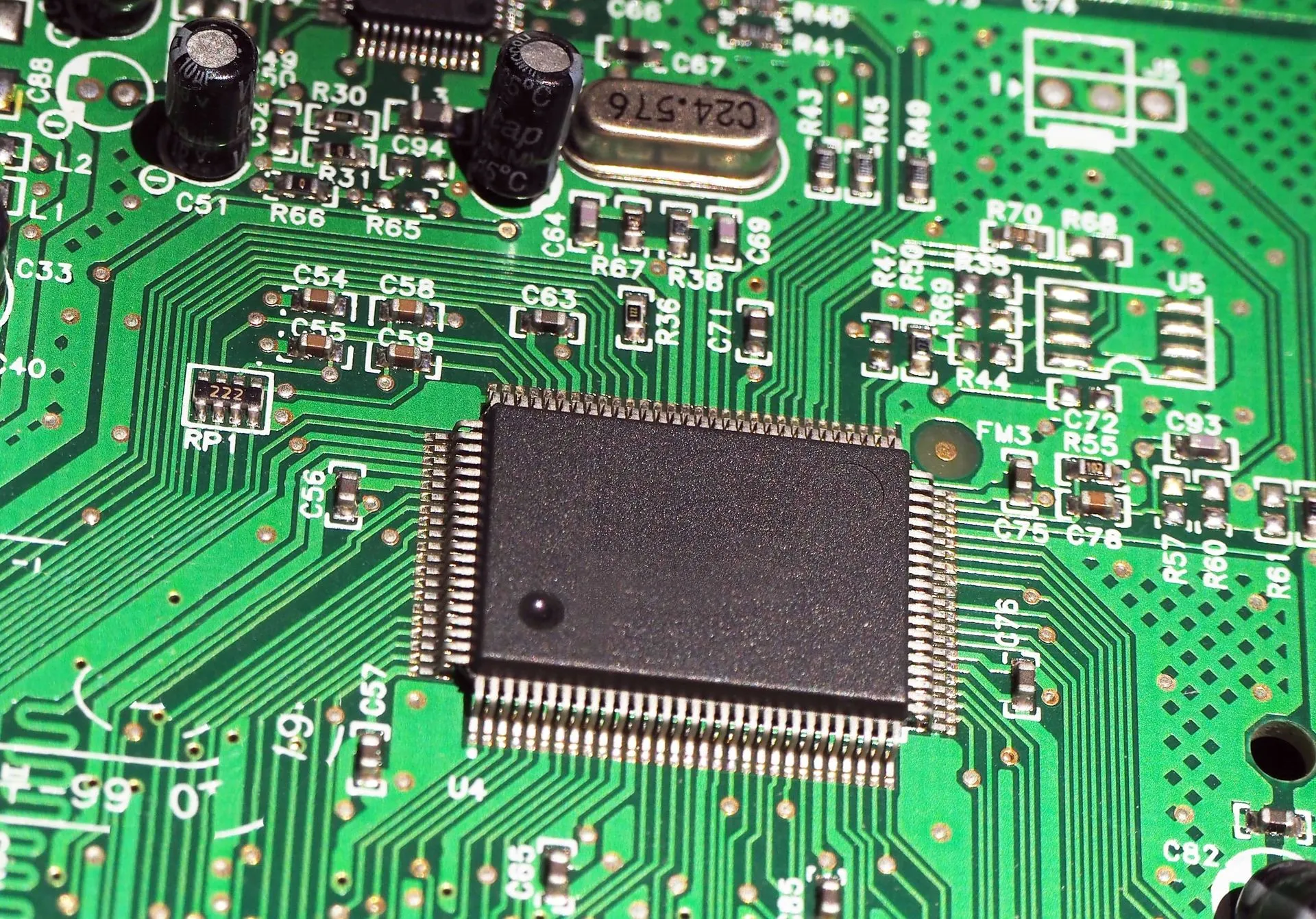
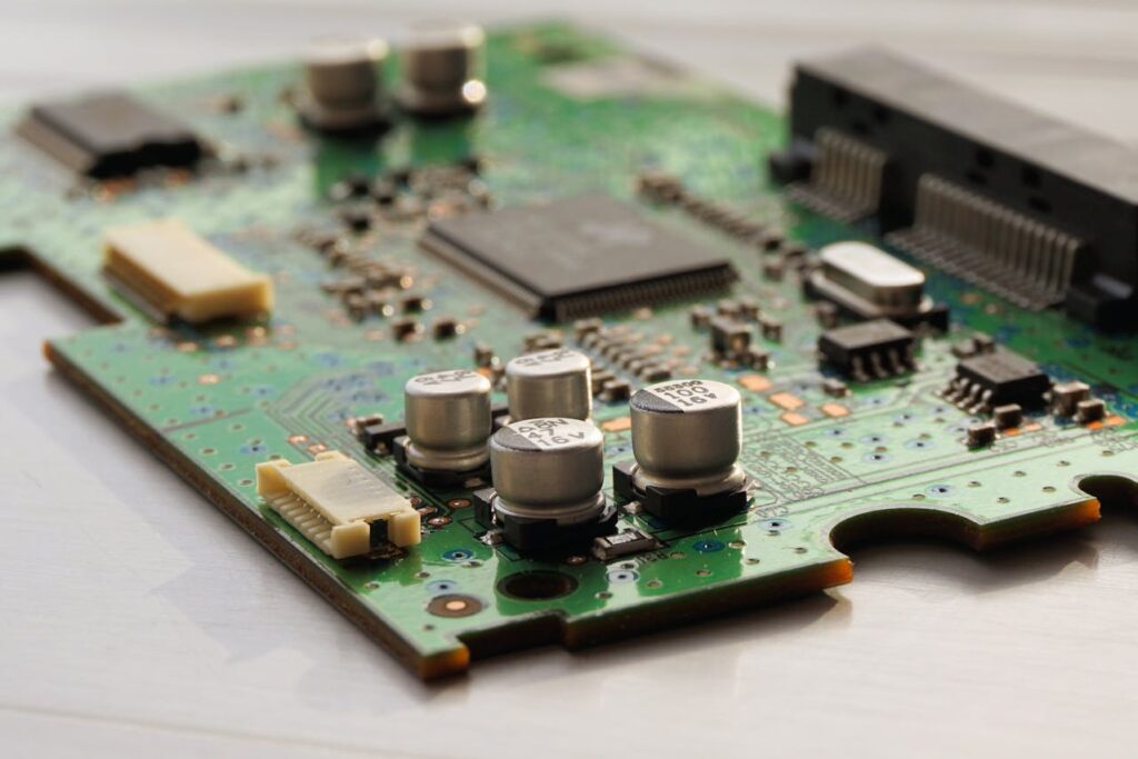
A Printed Circuit Board Assembly (PCBA) is the process of attaching electronic components onto a Printed Circuit Board (PCB) to create a fully functional electronic circuit. Unlike a bare PCB, which only provides the foundation for electrical pathways, a PCBA includes all the necessary components that make the circuit operational, such as resistors, capacitors, integrated circuits, and connectors.
In essence, while a PCB serves as the skeleton, a PCBA is the fully built and functional “body” of an electronic device.
How is a PCBA Made?
The assembly process involves a few key steps that transform a plain PCB into a working board:
- Placing the Components:
First, all the tiny electronic parts are added to the PCB. This can be done using machines for precision and speed. The components are placed on the board using one of two methods:
- Surface-Mount Technology (SMT): Components are placed directly on the surface of the board.
- Thru-Hole Technology: Components are inserted into holes drilled in the board for extra durability.
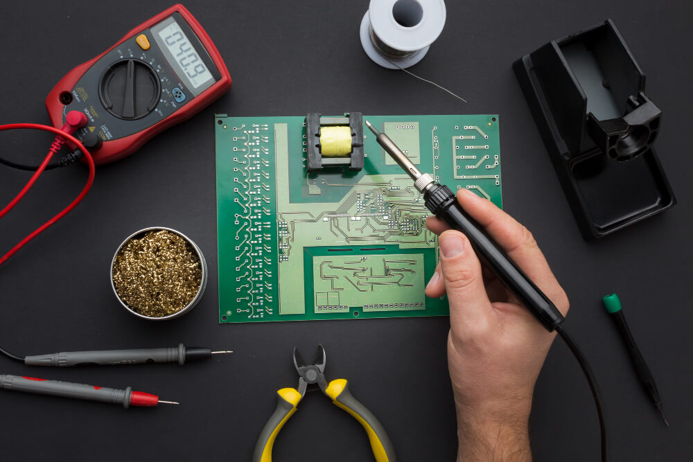
- Soldering: After the components are in place, they need to be secured. This is done by melting solder to create strong connections:
- For SMT components, the board is heated in a reflow oven, which melts the solder paste applied earlier.
- For thru-hole components, the board is passed over a wave of molten solder to bond the parts.
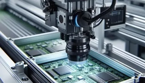
- Inspection and Testing: Once everything is soldered, the board is carefully checked. Machines or technicians inspect the connections to make sure nothing is out of place or faulty. Finally, the board is tested to ensure it works as it should.
Types of PCBAs
Printed Circuit Board Assemblies (PCBAs) are classified based on the method used to attach components to the board. Here’s an overview of the three main types:
1. Surface-Mount Technology (SMT)
- In Surface-Mount Technology, electronic components are mounted directly onto the surface of the PCB without the need for drilling holes. This is the most widely used method in modern electronics.
- Features:
- Compact and lightweight design.
- Enables high-density component placement.
- Faster assembly process using automated machines.
- Reduced manufacturing costs.
- Applications:
Used in consumer electronics like smartphones, tablets, and wearables, as well as industrial automation systems.
2. Thru-Hole Technology
- Thru-Hole Technology involves inserting component leads into pre-drilled holes on the PCB and soldering them to pads on the opposite side. This method provides robust mechanical connections.
- Features:
- Stronger component attachment, suitable for environments with high stress or vibration.
- Larger components can be mounted.
- Requires more space and manual labor compared to SMT.
- Applications:
Common in power electronics, automotive applications, and military equipment where durability is critical.
3. Mixed Technology
- Mixed Technology combines both SMT and Thru-Hole components on the same PCB to leverage the strengths of each method.
- Features:
- Balances high-density design with robust component connections.
- Ideal for complex circuits requiring varied component types.
- Allows flexible designs for specialized applications.
- Applications:
Used in advanced electronic devices, such as telecommunications equipment, medical devices, and aerospace systems.
PCB vs PCBA: Key Differences Table
| Aspect | PCB (Bare PCB) | PCBA (Assembled PCB) |
| Definition | A Printed Circuit Board (PCB) is an empty board made of non-conductive material with etched copper traces to provide pathways for electrical signals. It has no electronic components attached. | A Printed Circuit Board Assembly (PCBA) is a PCB with all the required electronic components mounted, making it functional as part of an electronic device. |
| Functionality | Acts as a passive structure that provides physical support and electrical routing for components but cannot perform any electronic task on its own. | Functions as an active assembly, capable of performing specific tasks, such as processing signals, power management, or communication in electronic devices. |
| Complexity | Simple in design, consisting of multiple layers (single, double, or multi-layer) with copper pathways for electrical connectivity. It does not include additional complexity from electronic parts. | More complex, as it involves mounting and soldering various components like resistors, capacitors, ICs, and connectors. The complexity depends on the number and type of components used. |
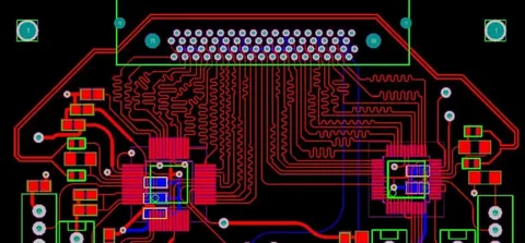
| Manufacturing Process | Fabrication process includes designing the circuit layout, etching copper layers, drilling holes, applying solder masks, and adding silkscreen for labeling. | Assembly process involves placing components onto the PCB using Surface-Mount Technology (SMT) or Thru-Hole Technology, soldering the parts, inspecting for quality, and testing functionality. |
| Components | No electronic components are present; it only includes the physical board with copper traces and protective layers like solder mask and silkscreen. | Includes all electronic components, such as resistors, capacitors, diodes, transistors, and microchips, mounted onto the PCB. |
| Cost | Lower cost as it involves only the board fabrication and no additional materials or assembly labor. | Higher cost due to component procurement, assembly processes, and quality testing requirements. |
| Applications | Used as a base for assembling circuits in various devices. On its own, it serves no functional purpose. | Used in fully functional devices such as smartphones, computers, medical equipment, and automotive systems. |
| Durability | Durable as a physical structure, but it is vulnerable to damage without protective components. | More robust, as it includes components that enhance the board’s functionality and protection mechanisms, such as integrated circuits. |
| Testing | No functional testing required since it is just the board. Only physical checks for defects in layers and traces are conducted. | Undergoes rigorous functional testing, such as Automated Optical Inspection (AOI), X-ray, and live performance tests to ensure it works as intended. |
PCB vs PCBA in Electronic Equipment
Examples of Devices with PCBs and PCBAs
- Devices with PCBs: PCBs are present in almost every electronic device, but when they’re bare, they’re mainly used as the foundation for assembling circuits.
Examples:
- Prototyping boards for testing circuit designs.
- LED light strips or basic circuits used in small, low-cost gadgets.
- Devices with PCBAs:
PCBAs are what make electronic devices functional. Once components are added to a PCB, it becomes a PCBA that powers devices like:
- Smartphones: Enabling all the functions from calls to apps.
- Computers: With PCBAs for motherboards, graphics cards, and power supplies.
- Cars: Controlling systems like braking, engine management, and infotainment.
- Medical devices: Found in diagnostic machines like MRIs and portable health monitors.
Why Both Are Essential for Electronic Functionality
- PCBs: A PCB acts as the foundation, providing a stable platform and pathways for electrical signals. Without it, circuits would be chaotic and inefficient, making compact and reliable electronics impossible.
- PCBAs: A PCBA takes that foundation and turns it into the brain of the device by adding components like resistors, capacitors, and microchips. This is what allows a device to perform its intended functions, from processing data to controlling power.
- Working Together: PCBs and PCBAs depend on each other. The PCB provides structure and organization, while the PCBA adds the components that bring the device to life. Without one, the other wouldn’t function.
Summary/Conclusion
While a PCBA is the completed product, with all the components that go into making it functional-the “furniture” in a house—a PCB is much like the framing of a house, serving as the structure and paths for electrical circuits. PCBs and PCBAs taken together provide the basis and functioning of contemporary electronics: running everything from basic devices to sophisticated medical and industrial systems. Interdependence is the guarantee of dependability, performance, and efficiency—that is, of essentially indispensable daily tools. Modern technology simply cannot exist as we know it without the harmonic functioning of both PCB vs PCBA taken together.
FAQs
What is the difference between PCB and PCBA?
A PCB is a bare board providing structure and pathways for electrical connections, while a PCBA is a PCB with components mounted, making it functional.
Which is more expensive: PCB or PCBA?
A PCBA is more expensive due to the additional cost of components, assembly processes, and testing, compared to the simpler manufacturing of a PCB.
How do I choose the right PCBA manufacturer?
Look for a manufacturer with industry experience, certifications (ISO, IPC-A-610), advanced assembly capabilities (SMT/Thru-Hole), robust quality control, reasonable costs, and good customer support.