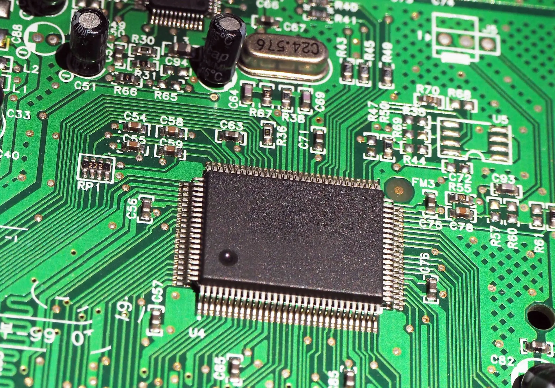
Capacitors are integral components in electronic circuits, serving various functions such as smoothing power supplies, filtering signals, and coupling signals between stages. Over time, capacitors can degrade or fail, leading to circuit malfunctions. Testing a capacitor in circuit is a crucial skill for electronics enthusiasts and professionals alike. This comprehensive guide will walk you through the process of testing a capacitor in circuit, ensuring your devices operate optimally.
Understanding Capacitor in Circuits
Before delving into testing methods, it’s essential to understand what capacitor in circuits. Capacitors store and release electrical energy, acting as temporary batteries. They are characterized by their capacitance value (measured in Farads), voltage rating, and equivalent series resistance (ESR). In-circuit testing helps determine if a capacitor is functioning within its specified parameters without the need for complete disassembly.
Safety Precautions Before Testing
Testing capacitors involves working with electrical components, so safety is paramount:
- Power Down the Circuit: Always ensure the circuit is powered off before testing to prevent electrical shock or damage to the multimeter.
- Discharge the Capacitor: Even when powered off, capacitors can retain charge. Use a resistor (typically 10kΩ to 100kΩ, 1W) to discharge the capacitor safely.
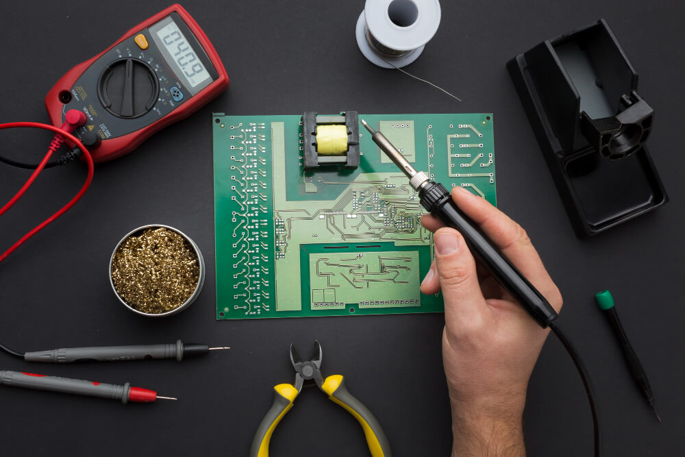
- Use Proper Tools: Employ a digital multimeter (DMM) with capacitance measurement capabilities for accurate results.
Methods for Testing a Capacitor in Circuit
Visual Inspection
Start with a visual check to identify obvious issues:
- Bulging or Leaking: Swollen tops or bottoms, or any leakage, especially in electrolytic capacitors, indicate failure.
- Discoloration or Burn Marks: Signs of overheating or damage.
- Cracks or Physical Damage: Structural integrity issues.
While visual inspection won’t detect all problems, it’s a quick first step.
Using a Digital Multimeter (DMM)
A DMM can measure capacitance, resistance, and sometimes ESR. Here’s how to use it:
- Set to Capacitance Mode: Turn the dial to the capacitance (C) symbol.
- Connect the Probes: Attach the multimeter probes to the capacitor terminals (observe polarity for polarized capacitors).
- Read the Display: Compare the measured value with the capacitor’s rated capacitance. A significant deviation suggests a faulty capacitor.
Note: Some DMMs can also measure ESR, which is crucial for assessing the health of electrolytic capacitors.
Resistance Measurement
This method assesses the capacitor’s ability to charge and discharge:
- Set to Ohms (Ω): Choose a high resistance range.
- Connect the Probes: Attach the probes to the capacitor terminals.
- Observe the Reading:
- Initial Low Resistance: Indicates charging.
- Rising Resistance: Should approach infinity (OL) as the capacitor charges.
- Constant Low Resistance: Suggests a shorted capacitor.
- No Change: Indicates an open capacitor.
This test is effective for detecting shorted or open capacitors but doesn’t provide information on capacitance or ESR.

ESR (Equivalent Series Resistance) Measurement
ESR (Equivalent Series Resistance) is a critical parameter, especially for electrolytic capacitors:
- Use an ESR Meter: This specialized tool applies a small AC signal to the capacitor and measures the resulting impedance.
- In-Circuit Testing: ESR meters can often test capacitors without removing them from the circuit.
- Interpret the Reading: High ESR values indicate degraded performance, even if the capacitance is within tolerance.
Note: ESR meters are particularly useful for power supply circuits where high ESR can lead to instability or failure.
Interpreting Test Results
After performing the tests, analyze the results:
- Capacitance Test: A significant deviation from the rated value indicates a faulty capacitor.
- Resistance Test: A constant low resistance suggests a short; no change suggests an open.
- ESR Test: High ESR values (typically above 1Ω for large capacitors) indicate poor performance.
When to Replace a Capacitor
Consider replacing a capacitor if:
- Visual Defects: Bulging, leaking, or physical damage.
- Test Results: Significant deviation in capacitance, low resistance, or high ESR.
- Circuit Malfunction: Persistent issues in the circuit that align with capacitor failure symptoms.
Conclusion
Testing a capacitor in circuit is an essential skill for diagnosing and resolving issues in electronic systems. Whether you’re performing a visual inspection, using a digital multimeter, or leveraging specialized tools like ESR meters, each method offers valuable insights into the capacitor’s condition. Understanding how to test capacitors in circuit without removing them saves time, prevents unnecessary component replacements, and ensures the ongoing reliability of your electronic devices.
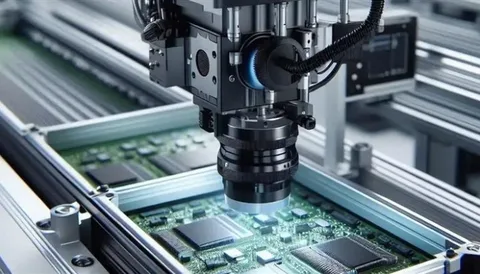
At Qual-Pro, we understand the critical role capacitors play in circuit performance. Our commitment to quality and precision ensures that every component in your assemblies is thoroughly tested and verified. By integrating best practices and advanced testing techniques, Qual-Pro helps clients maintain product integrity and avoid costly failures.
Choose Qual-Pro for trusted expertise in electronics manufacturing and capacitor testing—where quality meets performance.