When dealing with ceramic capacitors, understanding how to read their values is essential for anyone working with electronics, whether you’re a beginner or an experienced technician. Ceramic capacitors are widely used in various electronic circuits, and knowing how to correctly interpret their markings can save time and reduce errors during assembly or troubleshooting. In this article, we will guide you through the process of understanding and reading ceramic capacitor values effectively.
What Is a Ceramic Capacitor?
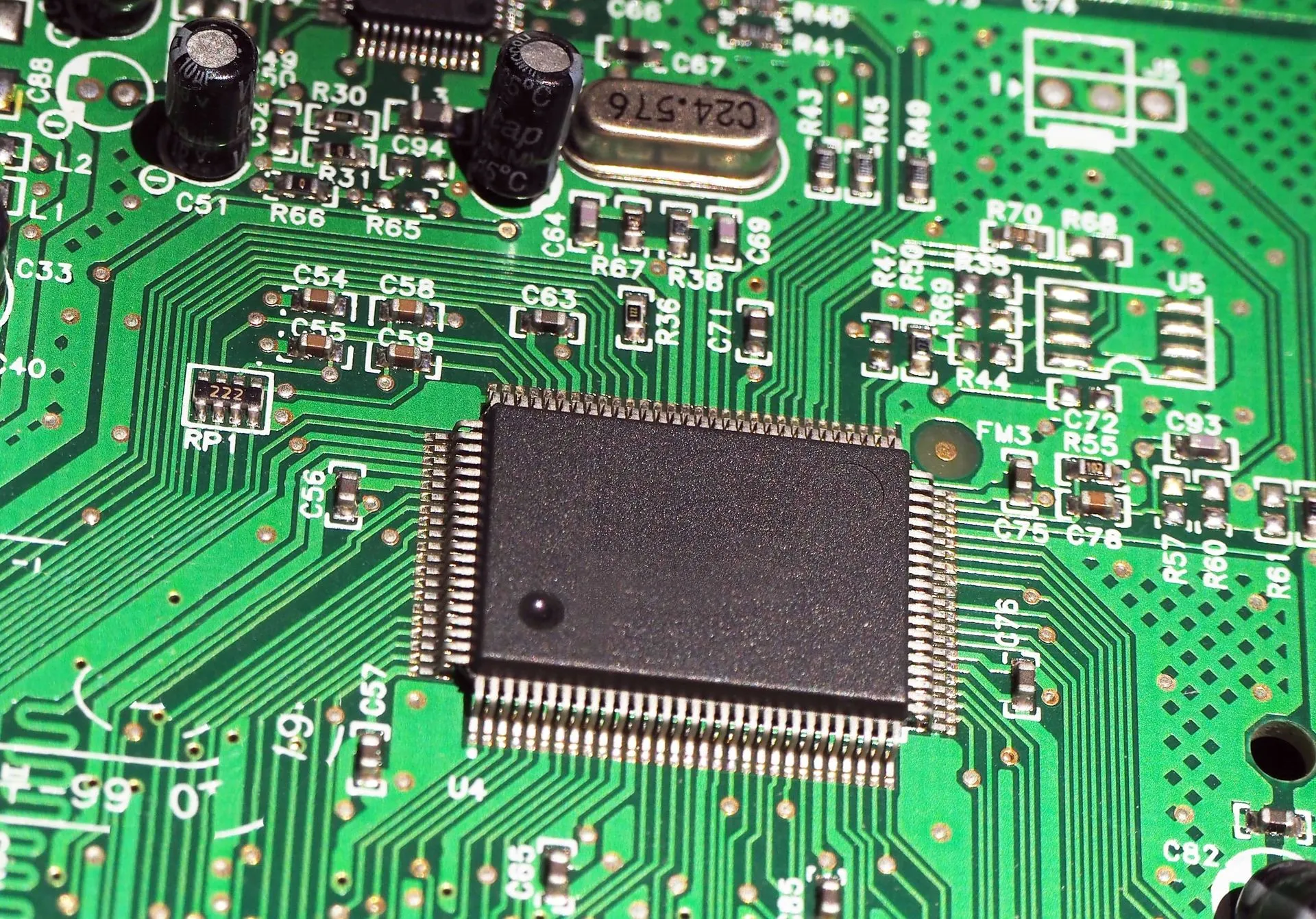
A ceramic capacitor is a type of capacitor that uses a ceramic material as its dielectric. It is commonly found in electronic devices like radios, televisions, and even power supplies. The capacitor’s primary role is to store electrical energy temporarily and release it when needed. Its capacity is measured in farads (F), with typical values in the picofarad (pF), nanofarad (nF), and microfarad (µF) ranges. The process of reading and understanding the ceramic capacitor value is key for ensuring the proper functionality of your circuit.
Understanding Ceramic Capacitor Markings
Ceramic capacitors are typically marked with a three-digit code that indicates their capacitance value, tolerance, and voltage rating. Let’s break down how to read these markings effectively:
1. The Three-Digit Code for Capacitance
The first part of the marking on a ceramic capacitor consists of three digits. These digits represent the capacitance value in picofarads (pF). The first two digits indicate the first part of the value, while the third digit represents how many zeros should be added after it.
For example:
- 104: The first two digits “10” represent 10, and the third digit “4” indicates that four zeros should be added. Thus, the capacitance value is 100,000 pF, or 0.1 µF.
2. Tolerance Code
After the capacitance value, you may notice a letter. This letter represents the tolerance of the ceramic capacitor. Tolerance indicates how much the actual value of the capacitor can vary from the nominal (stated) value. The most common tolerance codes are:
- J: ±5%
- K: ±10%
- M: ±20%
For example, a marking like 104J indicates a capacitance of 0.1 µF with a tolerance of ±5%.
3. Voltage Rating
In addition to the capacitance and tolerance, ceramic capacitors also have a voltage rating, which is typically marked as a number followed by “V” (for volts). The voltage rating tells you the maximum voltage the capacitor can safely handle before it risks damage or failure. For instance, a marking like 50V means the capacitor can safely handle a voltage up to 50 volts.
Types of Ceramic Capacitors and Their Value Markings
1. Multilayer Ceramic Capacitors (MLCC)
MLCCs are the most commonly used type of ceramic capacitor. They have multiple layers of ceramic material, which increases their capacitance without increasing their size. The value marking system we discussed earlier is most commonly used for MLCCs, making them easy to identify and use.
2. Disc Ceramic Capacitors
Disc capacitors are often marked similarly to MLCCs, but they tend to be bulkier and have a different form factor. These capacitors are primarily used in applications where higher voltage or higher capacitance values are required. The markings will include the three-digit code for capacitance, tolerance, and sometimes the voltage rating.
How to Read Ceramic Capacitor Value with Examples
Let’s look at some common examples of ceramic capacitor values and how to interpret them:
100nF Ceramic Capacitor
If the capacitor is marked 104, it represents a capacitance value of 100nF (nanofarads) or 0.1µF. This value is standard for many filtering and decoupling applications in electronics.
220pF Ceramic Capacitor
A capacitor with the marking 221 represents a capacitance value of 220pF. The “22” signifies 22, and the “1” indicates one zero, giving a capacitance of 220pF.
47nF Ceramic Capacitor
A 473 marking indicates a capacitance of 47nF. It’s important to understand that nF is often used for higher values in ceramics, especially when working with MLCC designs.
1µF Ceramic Capacitor
Capacitors marked as 105 are rated for 1µF capacitance. Again, the first two digits, “10”, represent 10, and the last digit “5” tells us to add five zeros, equating to 1 µF.
How to Calculate Ceramic Capacitor Value in Different Units
Sometimes you may encounter capacitors with different units, such as picofarads (pF), nanofarads (nF), or microfarads (µF). Understanding these units and how to convert them is essential for ensuring you’re using the correct component.

- 1 µF (microfarad) = 1,000 nF (nanofarads)
- 1 nF = 1,000 pF (picofarads)
For example:
- 0.1 µF = 100 nF = 100,000 pF
- 1 nF = 1,000 pF
Factors to Consider When Choosing a Ceramic Capacitor
When selecting a ceramic capacitor, it’s not just about the capacitance value; you should also consider the following factors:
1. Voltage Rating
Ensure the voltage rating of the capacitor exceeds the maximum operating voltage of the circuit to avoid breakdown or failure.
2. Tolerance
Choose the appropriate tolerance level for your application. Tight tolerances are needed in precise applications like timing circuits, while wider tolerances are acceptable in power supplies or filtering applications.
3. Temperature Coefficient
Ceramic capacitors can have different temperature coefficients (how their value changes with temperature). Common types include Class I, Class II, and Class III ceramics. Class I provides the most stable capacitance, while Class III offers high capacitance but with greater variations in value over temperature changes.
Why Accurate Ceramic Capacitor Value Reading Is Important
Accurately reading ceramic capacitor values is critical in electronic design for several reasons:
- Performance: Using a capacitor with the wrong value can lead to improper filtering or timing issues.
- Reliability: Incorrectly chosen capacitors may fail prematurely or even cause circuit damage.
- Efficiency: Ensuring the correct ceramic capacitor value helps optimize the performance and energy consumption of your device.
Conclusion
In conclusion, understanding how to read ceramic capacitor values is an essential skill for anyone working with electronics. By decoding the three-digit code on the capacitor, considering the tolerance and voltage ratings, and selecting the correct type of ceramic capacitor for your project, you can ensure optimal performance and reliability in your circuits. With the information provided, you now have the tools to confidently interpret ceramic capacitor values and apply them correctly in your designs. Trust Qual-Pro to provide you with high-quality components and support for all your electronic needs.