Designing and building a mechanical keyboard PCB is one of the most rewarding DIY projects for tech enthusiasts, electronics hobbyists, and anyone looking to create a highly personalized typing experience. From choosing your layout to programming the firmware, each step offers a level of customization that off-the-shelf keyboards simply can’t match.
In this comprehensive guide, we’ll walk you through how to make a keyboard PCB from scratch, covering everything from keyboard matrix wiring for beginners to programming your custom PCB with Qual-pro. Whether you’re dreaming of a DIY hot-swappable keyboard PCB or a simple wired design, this tutorial will help you bring your vision to life.
Why Build a Custom Keyboard PCB?
The Rise of DIY Keyboards
DIY keyboards have surged in popularity among enthusiasts who want to tailor every aspect of their typing experience. A custom keyboard allows you to choose your switches, stabilizers, keycaps, and even specialized layouts like ergonomic splits. By building the PCB yourself, you gain complete control over the design, from the circuit matrix to the placement of components like the microcontroller.
Advantages of a Homemade Mechanical Keyboard
- Full Customization: Design your keyboard PCB layout, switch footprint, and mounting style to match your preferences.
- Optimal Typing Experience: Improve ergonomics by placing keys and function layers exactly where you want them.
- Learning Opportunity: Gain hands-on experience in electronics, PCB design, and firmware programming.
- Satisfaction & Community: Join a vibrant community of keyboard enthusiasts and share your creations.
Planning Your Custom Keyboard PCB
Determining the Layout
Start by choosing a layout that suits your needs:
- Full-Size (104/105 Keys): Includes a numpad and function row.
- Tenkeyless (TKL): Omits the numpad for a more compact design.
- 60%, 65%, 75%: Compact layouts that retain essential keys.
- Ergonomic/Split Layouts: Ideal for reducing strain during long typing sessions.
Choosing the Switches
Select switches based on your typing preferences:
- Linear: Smooth keystrokes (e.g., Cherry MX Red).
- Tactile: Bumpy feedback (e.g., Cherry MX Brown).
- Clicky: Audible and tactile feedback (e.g., Cherry MX Blue).
Decide whether you want soldered switches or hot-swappable sockets for easy switch replacement.
Selecting the Microcontroller
Choose a microcontroller with good community support, such as:
- Atmel ATmega32U4: Popular for its USB interface and QMK compatibility.
- STM32 Series: ARM-based MCUs with more power and flexibility.
Adding Extra Features
Consider features like:
- RGB Lighting: Add per-key RGB or underglow for a visually stunning keyboard.
- Wireless/Bluetooth: Incorporate wireless functionality for a cable-free setup.
- Encoder Wheels: Add knobs for volume control or macros.
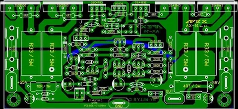
Designing the Schematic
Software: KiCad or Eagle
Use PCB design software like KiCad (free and open-source) or Eagle to create your schematic. These tools allow you to define the keyboard matrix, place components, and route traces.
Keyboard Matrix Wiring Explained
The keyboard matrix is the foundation of your PCB design:
- Rows and Columns: Assign microcontroller pins to rows and columns.
- Diodes: Place a diode on each switch to prevent ghosting and ensure accurate keypress detection.
- Scanning: The microcontroller scans rows and columns to detect keypresses.
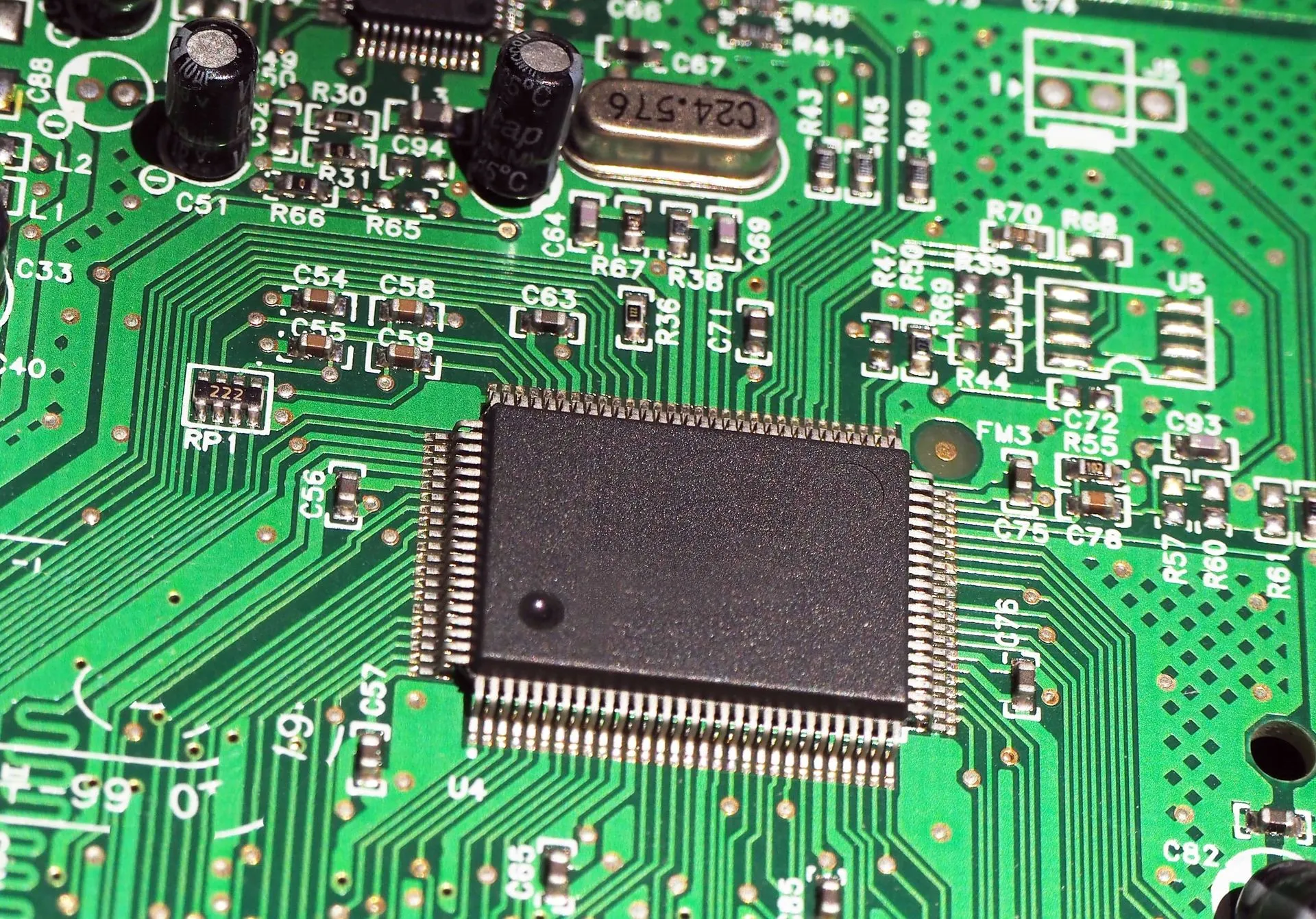
Supporting Components
Include essential components in your schematic:
- Microcontroller: Ensure proper pin assignments for rows, columns, and additional features.
- Power Supply: Add decoupling capacitors for stable voltage.
- USB Connector: Use USB-C or micro USB for connectivity.
- Reset and Programming Headers: Simplify firmware flashing and debugging.

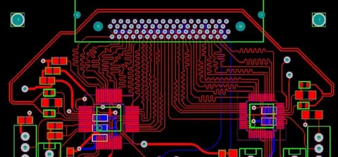
PCB Layout
Placing Components
- Switches: Place switch footprints according to your layout, typically with 19.05mm spacing.
- Microcontroller: Position it near the USB connector for easy routing.
- Diodes: Place diodes close to each switch for clean matrix wiring.
Routing Traces
- Matrix Traces: Connect diodes to rows and columns with clean, organized traces.
- USB Data Lines: Keep D+ and D– lines short and paired for optimal performance.
- Power and Ground Planes: Use a ground plane to reduce noise and ensure stable operation.
Checking Clearance and Gerbers
Generate Gerber files for manufacturing. Double-check your design for:
- Component Overlaps: Ensure no parts are too close together.
- Drill Holes: Verify hole sizes for switches and connectors.
- Silkscreen Labels: Add clear labels for easier assembly.
Manufacturing the PCB
Choosing a PCB Manufacturer
Popular options include:
- JLCPCB: Affordable and beginner-friendly.
- PCBWay: High-quality manufacturing with fast turnaround.
- OSH Park: Great for small batches and prototyping.
Ordering Details
Specify:
- Layers: Most keyboard designs use 2 or 4 layers.
- Thickness: 1.6mm is standard, but 1.2mm can be used for slimmer builds.
- Surface Finish: Choose HASL or ENIG for durability.
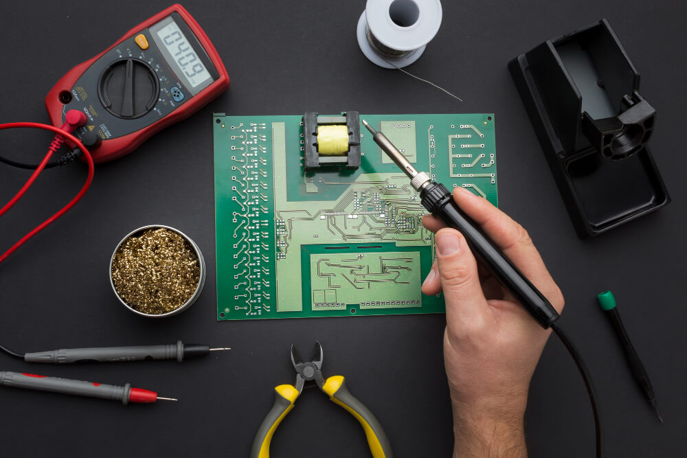
Soldering and Assembly
Soldering Components
- Diodes: Ensure correct orientation (cathode toward the switch).
- Microcontroller: Align pins carefully and solder securely.
- Hot-Swap Sockets: Install sockets if you want a hot-swappable design.
Mounting Switches and Stabilizers
- Stabilizers: Install stabilizers for larger keys like Spacebar and Enter.
- Switches: Press switches into the PCB or solder them in place.
Programming Your Keyboard
Using QMK Firmware
QMK is a popular open-source firmware for custom keyboards. Follow these steps:
Clone QMK Repository: Download the QMK firmware from GitHub.
Create a Keyboard Folder: Define your keyboard layout and keymap.
Compile and Flash: Use the QMK CLI to compile and flash your firmware to the microcontroller.
Testing
Test each key using a key tester or text editor. Address any issues with solder joints, diodes, or firmware configuration.
Common Mistakes to Avoid
- Incorrect Diode Orientation: Double-check diode placement to avoid non-functional keys.
- Poor USB Routing: Keep USB data lines short and paired.
- Insufficient Grounding: Use a ground plane to reduce noise.
- Overcomplicating the Matrix: Stick to a simple row-and-column design for your first project.
Adding RGB Lighting
To add RGB lighting:
- Per-Key RGB: Use individually addressable LEDs like WS2812B or SK6812.
- Underglow: Place LEDs along the edges of the PCB for a glowing effect.
- Firmware Support: Ensure your firmware supports RGB lighting and configure it in QMK.
Conclusion
Building a custom keyboard PCB is a challenging but rewarding project that combines electronics, design, and programming. By following this guide, you’ll learn how to design a keyboard PCB, assemble your keyboard, and program it with custom firmware. Whether you’re creating a simple wired keyboard or a feature-rich hot-swappable design, the process will deepen your understanding of electronics and give you a unique tool tailored to your needs.
With the right tools, resources, and perseverance, you’ll soon be typing on a keyboard that you designed and built from scratch. Enjoy the journey, and welcome to the world of custom keyboards!