Testing resistance in a circuit is a fundamental skill for anyone working with electronics, from beginners to seasoned professionals. Whether you’re troubleshooting faulty components, verifying circuit integrity, or designing new electronics, accurately measuring resistance helps ensure your circuit functions properly. In this detailed guide, you will learn the step-by-step process of testing resistance in a circuit, the tools required, and best practices to get reliable results.
What Is Resistance in a Circuit?
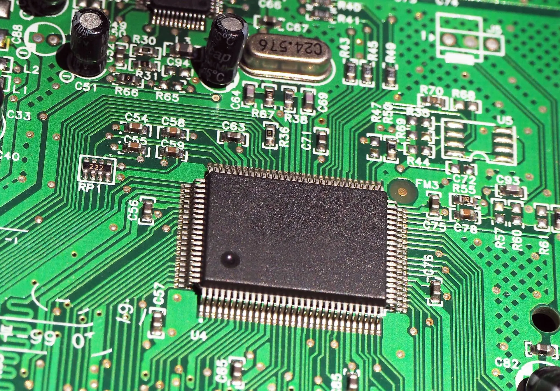
Before diving into testing methods, it’s important to understand what resistance in a circuit means. Resistance is a property of electrical components that opposes the flow of electric current. It is measured in ohms (Ω) and influences how much current can pass through the circuit for a given voltage.
In practical terms, resistance controls the flow of electricity, protecting components and regulating performance. For example, resistors in a circuit limit current to LEDs, preventing damage.
Why Test Resistance in a Circuit?
Testing resistance helps you:
- Identify faulty components such as resistors, wires, or connectors
- Detect short circuits or open circuits
- Verify the condition of circuit paths before powering devices
- Ensure components meet their specified resistance values
- Aid in circuit troubleshooting and maintenance
Tools Needed to Test Resistance in a Circuit
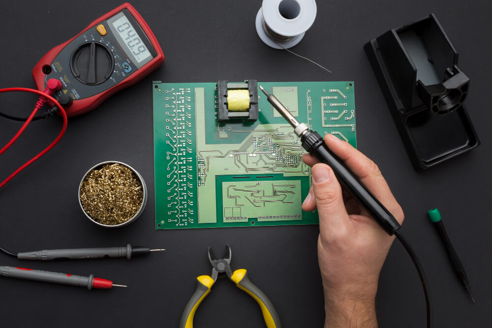
To accurately test resistance in a circuit, you’ll need a few essential tools:
- Multimeter: The most common and versatile tool used for measuring resistance. Digital multimeters (DMM) are preferred due to their ease of use and precision.
- Test Leads: Usually comes with the multimeter; these allow you to connect the meter to the circuit.
- Soldering Tools (optional): Sometimes, you may need to remove components for isolated testing.
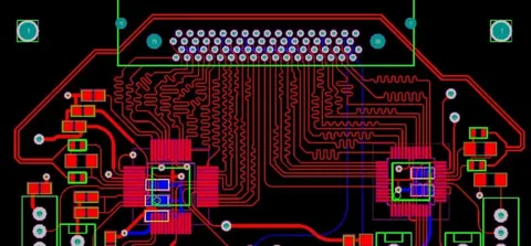
- Circuit Diagram or Schematic (recommended): Helps understand where to test resistance for accurate troubleshooting.
Step-by-Step Guide to Testing Resistance in a Circuit
Power Off the Circuit
Before testing resistance, ensure the circuit is completely powered off and unplugged from any power source. Measuring resistance in a live circuit can damage your multimeter or give inaccurate readings.
Discharge Capacitors
Capacitors can hold charge even after power is removed, which may affect your readings. Safely discharge capacitors by shorting their leads using a resistor or a discharge tool.
Set Your Multimeter to Resistance Mode (Ω)
Turn the dial on your multimeter to the resistance measurement setting, usually marked with the omega (Ω) symbol. Depending on your meter, select an appropriate range or set it to auto-range if available.
Test the Multimeter Leads
Touch the multimeter leads together and observe the reading. It should be close to 0 Ω, indicating the leads and meter are functioning correctly.
Connect Test Leads to the Circuit Points
Identify the two points in the circuit where you want to measure resistance. Place one probe on each point carefully. For example, if you are measuring the resistance of a resistor, touch the probes to each end of the resistor.
Read the Resistance Value
Observe the value displayed on the multimeter. This is the resistance between the two points. Compare the reading to the expected resistance from the circuit schematic or component specifications.
Interpret the Results
- Low resistance (close to zero ohms): Indicates a good conductor or a short circuit.
- High resistance (infinite or OL on the multimeter): Indicates an open circuit or broken path.
- Expected resistance: Matches the value on the resistor or the circuit design.
Important Tips When Testing Resistance in a Circuit
- Isolate Components if Necessary: Sometimes other components connected in parallel or series can affect readings. Remove or isolate the component if you suspect inaccurate values.
- Avoid Testing Powered Circuits: Measuring resistance on a powered circuit can damage your equipment.
- Be Mindful of Parallel Paths: Parallel circuit paths can cause resistance readings to be lower than expected.
- Use the Correct Range on Manual Meters: Set the resistance range higher than the expected value to avoid damaging the meter.
Common Mistakes to Avoid When Measuring Resistance
- Testing resistance with the circuit powered on
- Not discharging capacitors, leading to false readings
- Misinterpreting low resistance as a good condition without considering parallel paths
- Using faulty or damaged test leads
- Ignoring temperature effects, as resistance can change with temperature
Advanced Methods for Testing Resistance in a Circuit
Using an LCR Meter
An LCR meter measures inductance (L), capacitance (C), and resistance (R) with higher accuracy than a basic multimeter. This tool is useful for complex circuits or precision measurements.
Testing On-Circuit vs. Off-Circuit
- On-Circuit Testing: Measuring resistance without removing the component. This is quicker but can lead to inaccurate readings due to other parallel elements.
- Off-Circuit Testing: Desoldering and removing the component for isolated testing. This provides more precise results.
Conclusion
Understanding how to test resistance in a circuit is essential for diagnosing, repairing, and designing electronic systems. At Qual-Pro, we believe that precision and safety are at the heart of every successful electronics project. With the right tools, proper techniques, and careful interpretation of results, you can effectively troubleshoot circuit issues and ensure each component performs exactly as intended.
At Qual-Pro, we emphasize the importance of powering down circuits before testing and isolating components when necessary to achieve accurate measurements. These practices not only safeguard your equipment but also contribute to reliable diagnostics.
Mastering resistance measurement with Qual-Pro’s guidance not only sharpens your electronics skills but also saves valuable time and resources by preventing costly mistakes early in the development or repair process. Whether you’re a technician, engineer, or hobbyist, understanding resistance in a circuit is a foundational skill that supports smarter, safer, and more efficient electronic solutions.