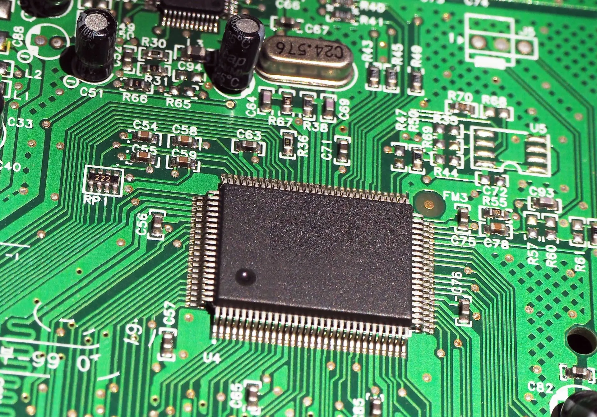
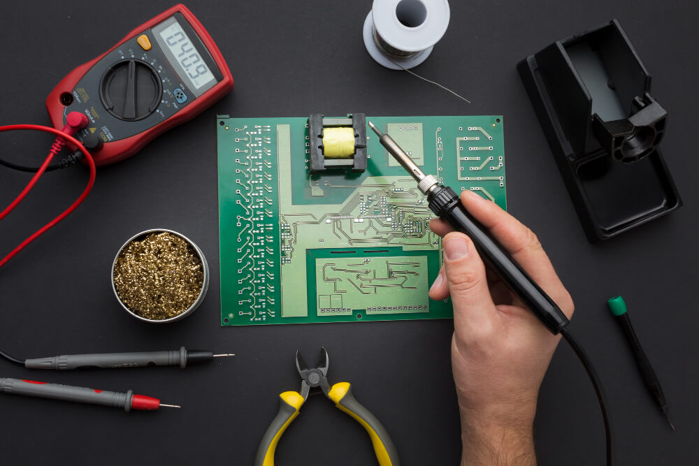
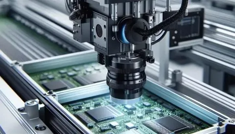
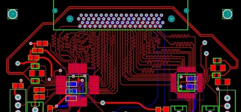
As technology rapidly evolves, the need for advanced printed circuit boards (PCBs) becomes more critical than ever. Among the many types of PCBs used in modern electronics, High-Frequency PCBs stand out for their essential role in high-speed and high-frequency applications. These boards are not just components—they’re the foundation of powerful, reliable performance in communication systems, radar, satellite, automotive radar, and wireless technologies.
In this ultimate guide, we’ll explore what High-Frequency PCBs are, how they’re made, why they matter, and how to choose the right type for your next project.
What Are High-Frequency PCBs?
High-Frequency PCBs are specialized circuit boards designed to handle signals at frequencies typically above 500 MHz. In applications such as RF (radio frequency) communication, radar, and high-speed data transfer, the integrity of signals becomes sensitive to even the slightest changes in material properties or design layout.
To ensure high performance and low signal loss, these boards use materials with controlled dielectric constant (Dk) and low dissipation factor (Df). Unlike traditional FR4 PCBs, high-frequency boards are engineered to maintain stable electrical performance across a wide frequency range.
Applications of High-Frequency PCBs
You’ll find High-Frequency PCBs in some of the most advanced technologies used today:
- Telecommunications: 5G base stations, antennas, and satellite communication devices
- Medical Devices: MRI scanners and diagnostic equipment
- Automotive Radar Systems: For lane detection and adaptive cruise control
- Aerospace & Defense: Radar and navigation systems
- Consumer Electronics: Wi-Fi routers and wireless audio systems
In each of these industries, signal integrity and consistent performance are crucial. Even minor design flaws or poor material choices can lead to massive losses in performance and reliability.
Key Characteristics of High-Frequency PCBs
To perform effectively in demanding environments, High-Frequency PCBs must meet stringent requirements. Let’s break down the most critical features:
1. Low Dielectric Constant (Dk)
The dielectric constant of a PCB material determines how quickly signals travel through it. Lower Dk values ensure faster signal transmission, which is essential for high-speed circuits and microwave PCBs.
2. Low Dissipation Factor (Df)
This measures how much signal energy is lost as heat. A low dissipation factor means minimal signal loss, which directly contributes to signal clarity and performance.
3. Thermal Stability
High-frequency applications often generate heat. Materials like PTFE and ceramic-filled laminates are favored for their ability to resist deformation and maintain electrical properties at high temperatures.
4. Tight Tolerances
Due to the sensitive nature of RF PCBs, design tolerances must be extremely tight. Any deviation in trace width, spacing, or material thickness can affect performance.
5. Controlled Impedance
Maintaining controlled impedance across the board is vital for signal consistency, especially in high-speed communication devices.
Materials Used in High-Frequency PCBs
Choosing the right substrate material is perhaps the most important step in designing High-Frequency PCBs. Here are some of the most commonly used materials:
PTFE (Polytetrafluoroethylene)
- Excellent electrical properties
- Stable dielectric constant
- Ideal for RF and microwave PCB applications
- Often reinforced with glass fiber for mechanical strength
Rogers Materials (e.g., RO4350B, RO3003)
- Designed specifically for high-frequency applications
- Consistent Dk and low Df
- Easier to fabricate than pure PTFE
Ceramic-Filled Laminates
- Good thermal performance
- Suitable for high-speed circuits
- Often used in military and aerospace applications
While FR4 is a cost-effective material for standard PCBs, it lacks the performance needed for High-Frequency PCBs, especially in demanding RF environments.
Challenges in Manufacturing High-Frequency PCBs
The production of High-Frequency PCBs is far more complex than that of standard boards. Here are a few of the key challenges:
Precision in Fabrication
High-frequency signals are highly sensitive to structural inconsistencies. Even small manufacturing defects can cause signal reflection or distortion.
Material Handling
PTFE and other advanced materials are difficult to drill and process compared to standard FR4. Specialized equipment and expertise are required to work with them.
Cost
High-performance materials and tight tolerance requirements make High-Frequency PCBs more expensive to produce. However, the investment is often justified by the improved performance and reliability.
Design Tips for High-Frequency PCBs
Designing a successful high-frequency board requires attention to several critical factors:
1. Keep Traces Short and Direct
Long signal paths increase the chances of interference and signal degradation. Use direct routing where possible to minimize loss.
2. Use Ground Planes
Ground planes help shield signals and reduce electromagnetic interference (EMI), a major concern in RF PCBs.
3. Impedance Matching
Design trace widths and spacing to match the required impedance. This helps in preserving signal strength and reduces reflection.
4. Minimize Via Usage
Each via introduces inductance and capacitance that can interfere with high-frequency signals. Use them sparingly and only where necessary.
5. Perform Signal Integrity Simulations
Before fabrication, run signal integrity simulations to predict how the board will perform in real-world conditions. This step helps identify and correct potential issues early in the process.
How to Choose the Right High-Frequency PCB Manufacturer
Selecting the right partner is critical for success in high-frequency applications. Look for a manufacturer with:
- Experience with RF and microwave PCBs
- Advanced testing and inspection equipment
- Proven track record in your industry
- Material expertise with PTFE, Rogers, and ceramic laminates
- In-house design and engineering support
Collaborating with a knowledgeable manufacturer ensures your board meets performance expectations and regulatory standards.
Future Trends in High-Frequency PCB Technology
The future of High-Frequency PCBs is closely tied to innovations in 5G, IoT, aerospace, and autonomous vehicles. As devices become smarter and faster, demand for more compact, reliable, and thermally efficient PCBs will grow.
Some emerging trends include:
- Integration of flexible and rigid-flex high-frequency PCBs
- Use of AI in signal integrity modeling
- Development of eco-friendly high-frequency materials
- Miniaturization of RF modules for wearable and portable tech
Staying ahead of these trends will be essential for engineers, manufacturers, and OEMs involved in high-frequency applications.
Conclusion
High-Frequency PCBs are the backbone of today’s most advanced electronic innovations. From 5G communication systems and automotive radar to aerospace and medical devices, these specialized circuit boards enable high-speed, high-precision performance where it matters most. Designing and manufacturing them requires deep expertise, the right materials, and attention to every detail—because even the smallest flaw can impact signal integrity and reliability.
At Qual-Pro, we specialize in delivering precision-engineered High-Frequency PCBs tailored to meet the demanding needs of modern industries. With decades of experience, advanced capabilities, and a commitment to quality, we help clients bring their most complex electronic designs to life—with confidence and consistency.
If you’re looking for a trusted partner to manufacture your next high-frequency PCB, Qual-Pro is ready to help you achieve the highest standards of performance and reliability.

